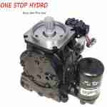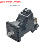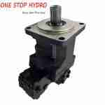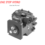
Typical structure of inclined (curved) axial piston pump
① Figure m of fixed displacement pump shows the structure of a2f series inclined shaft fixed displacement axial piston pump of Rexroth company in Germany, which is developed on the basis of a2f pump / motor. It can be used not only as hydraulic pump but also as hydraulic motor. The pump is composed of pump shell 2, back cover 8, drive spindle 1, mandrel 3, disc spring 4, spherical valve plate 6, plunger 10, cylinder block 11, etc. the pump adopts spherical valve plate, and tapered roller bearing group supports drive shaft and drive plate. Its biggest feature is that the original connecting rod plunger pair is replaced by conical plunger and piston ring seal. The angle between drive spindle and cylinder block axis increases from 25 ° to 40 °. As a result, the displacement increases by 52% and the torque increases by about 70%. The structure and process are simplified, the cost is reduced, and the volume and weight are reduced. However, the requirement of the pump for the cleanliness of the oil is increased. If the cleanliness of the oil does not meet the requirements, its service life will be shortened. The maximum pressure of the product is 45MPa and the displacement is 12-180ml / R. it is suitable for the open and closed hydraulic systems of engineering, metallurgy, mining, lifting and transportation, petroleum and other mechanical equipment.

② Figure n of variable displacement pump shows the structure of a7v series variable displacement piston pump of Rexroth company in Germany. Its core part structure is the same as a2f pump / motor. The main shaft 18 is driven to rotate, and the cylinder block 1 is driven to rotate through the connecting rod plunger pair 17, so that the plunger moves back and forth in a straight line in the cylinder block hole, realizing the action of oil suction and pressure. The pump has constant pressure variable, constant power variable and electric control proportional variable.

The variable mechanism of the pump shown in Figure n is composed of variable piston 4, pin 9, control valve core 8, valve sleeve 7, adjusting spring 6, adjusting screw 5, nozzle 15, pilot piston 14, guide rod 13, large and small springs 10 and 11, etc., which are installed in the back cover. The drive shaft and drive plate are supported by ball bearing group. The variable piston 4 is a stepped plunger. Its upper end diameter is smaller, which is called the small end of variable piston, while the lower end diameter is thicker, which is called the big end of variable piston. The large end of the variable piston has a transverse hole which passes through a pin. The left end of the pin is matched with the central hole of the valve plate, and the right end of the pin is sheathed on the guide rod. The upper chamber of the variable piston is high pressure and the lower chamber is low pressure, so it slides up and down under the pressure difference between the two ends, driving the valve plate to slide along the arc slide of the back cover, so as to change the angle between the cylinder axis and the main shaft. Therefore, when the spindle speed is constant, the output flow can be changed through the change of pressure.
The upper chamber of the variable piston is connected with the high-pressure oil of the pressure oil port through the oil passage, and the high-pressure oil is connected between the two steps of the control valve core 8. When the pressure is not high, the force of the pressure oil acting on the pilot piston and pushing the guide rod to the control valve core is less than or equal to the force of the adjusting spring, the high-pressure oil is sealed by the two steps of the control valve core, and the high-pressure oil cannot pass through the large cavity where the variable piston is located. At this time, the upper chamber of the variable piston is at high pressure and the lower chamber is at low pressure. Under the effect of pressure difference, the variable piston is at the lower end, that is, at the maximum swing angle and the maximum flow.
When the pressure increases, the high pressure oil acts on the upper end of the pilot piston through the nozzle and pushes the control valve core. As the driving force is greater than that of the adjusting spring, the control valve core moves downward, and the high-pressure oil flows into the lower chamber of the variable piston through a transverse hole. At this time, the pressure of the upper and lower ends of the variable piston is equal. Because the area of the lower end is larger than that of the upper end, the variable piston moves upward under the effect of the pressure difference between the two ends, so that the swing angle becomes smaller and the purpose of variable piston is realized. At the same time, the large and small springs on the guide rod are also under pressure. The pressure acts on the pilot piston through the guide rod, so that the force on the lower end of the pilot piston is balanced with the hydraulic pressure on the upper end, and the pressure of the guide rod on the control valve core is reduced. At this time, the spring force of the regulated spring on the lower end of the control valve core is greater than the pressure on the upper end of the guide rod, and it moves upward until the cross hole on the cut-off valve sleeve So the variable piston is fixed in a certain position. When the pressure is lower than a certain point on the constant power curve, the pressure transmitted to the pilot piston by the regulating spring acting on the control valve core and the guide rod is greater than the hydraulic pressure at the upper end of the pilot piston. The control valve core moves above the valve sleeve under the action of the regulating spring, connecting the control oil in the large chamber of the variable valve core with the low pressure chamber. The small end pressure of the variable piston is high, while the large end pressure is low, and the variable pressure is high The piston moves downward under the action of the pressure difference, which increases the swing angle between the cylinder block and the main shaft. At the same time, the pressure of the large and small springs on the pilot piston decreases, and the pilot piston pushes the guide rod and the control valve core downward under the action of the upper pressure until it is balanced with the force of the adjusting spring. At this time, the variable piston is in a new equilibrium state at a certain position.
When the pressure increases, the flow rate decreases and the pump changes from large swing angle to small swing angle; on the contrary, when the pressure decreases, the pump changes from small swing angle to large swing angle and the flow rate increases. Therefore, the product of flow and pressure can be kept constant, that is, constant power variable.
The pump adopts heavy load and long life bearing, which can be widely used in the hydraulic system of walking machinery and various industrial equipment. Figure o shows the physical shape of the inclined shaft variable displacement piston pump. The pressure is up to 40MPa, the displacement range is 20.5 ~ 500ml / R, and the maximum speed is 4750r / min.