Vane pump
3.1.1 type characteristics
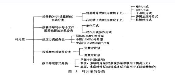
(1) Classified vane pump is a kind of shell pressure hydraulic pump with squeezer as blade. This kind of pump has a long history of development, and its rudiment can be found in many ancient water lifting tools at home and abroad. The detailed classification of vane pump is shown in Figure a.
(2) The characteristics are shown in the table below.
Characteristics of vane pump
| Main advantages | Main Disadvantages |
| ① Compact structure, large displacement per unit volume ② Single acting vane pump can be made into variable displacement pump and can be bi-directional variable, especially pressure compensated variable displacement pump with simple stator structure ③ Quantitative vane pump can be made into double acting or multi acting, with balanced bearing capacity and long service life ④ Multi acting vane pump has smaller flow pulsation and lower noise ⑤ Compared with plunger pump, Strong self priming ability ⑥ Both single acting vane pumps and double acting vane pumps can be made into double pump or even multi pump (two or more single stage pumps are installed together and connected in parallel on the oil circuit to form hydraulic pumps), thus meeting the different flow requirements of the hydraulic system | ① Poor anti pollution ability ② The rotor of a single acting vane pump bears a unidirectional hydraulic imbalance force, resulting in a short bearing life ③ The stator structure of a double acting or multi acting vane pump is complex ④ Due to the contact stress between the blade and the slide and the allowable sliding friction work, it is difficult to increase the pressure and speed of the variable vane pump. However, according to the requirements of centrifugal force required for blade extension, its speed cannot be too low, so the range of operating conditions is narrow |
3.1.2 working principle
(l) Working principle of single acting vane pump and some problems needing attention
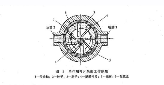
① Working principle the working principle of single acting vane pump is shown in Figure B. The outer surface of the rotor 2 and the inner surface of the stator 3 are cylindrical. An eccentricity e is maintained between the rotor center and the stator center. The rotor is provided with evenly distributed radial sliding slots, and the rectangular blade 4 is installed in the sliding slot of the rotor and can be flexibly retracted. These blades divide the annular space formed between the front and rear end covers and the rotor and stator into sealing working cavities with the same number of blades (all odd) along the circumference. Because the radial distance between the rotor and stator changes along the circumference, these seal cavities will expand and shrink periodically during the rotor rotation. A port plate with a waist shaped port window is installed in the pump, or a separated waist shaped port window is made on the end cover or stator of the pump. The oil suction cavity is connected with the working cavity which is expanding the volume, and the oil discharge cavity is connected with the working cavity which is reducing the volume. When the prime mover drives the rotor 2 to rotate in the direction shown in Fig. B through the transmission shaft 1, under the action of centrifugal force and pressure oil flowing into the blade root (some spring force), the blade on the right side stretches out, the top of the blade is close to the inner surface of the stator, the volume of the sealing working chamber increases gradually, creating a vacuum, and the oil is sucked in through the oil suction port and the right waist shaped flow distribution window. The left blade is retracted, and the volume of the sealing chamber is gradually reduced. The oil in the sealing chamber is pressed out through the left waist shaped flow distribution window and pressure port and transported to the system. The drive shaft drives the rotor to rotate once, and the working chamber of each seal absorbs and presses oil once. When the prime mover drives the pump to run continuously, the pump will press oil continuously.
② Some problems should be paid attention to
a. The variable problem is that the eccentricity e is maintained between the rotor center and the stator ring center of the single acting vane pump, and the pump displacement is related to the eccentricity P. if the eccentricity is adjusted by some mechanism, the oil supply displacement can be changed continuously or step by step from zero to the maximum value in a certain direction or from zero to the maximum value. If the direction of eccentricity e is changed, the suction and pressure chambers of the pump can be interchanged under the condition that the steering direction of the pump is not changed, so as to realize reverse oil supply. So single acting vane pump is often made into variable displacement pump. In addition, in order to meet the different flow requirements of the system, double pumps or even multi pumps are needed. They are hydraulic pumps installed in a shell by two or more single-stage pumps and connected in parallel on the oil circuit.
b. The problem of unbalanced force is due to the single direction hydraulic unbalanced force on the rotor, transmission shaft and bearing, the bearing load is large, the service life is short, and it is not suitable for high pressure, so the single acting vane pump is also called non unloading pump.
c. In order to make the top of the blade contact the inner surface of the stator reliably, the bottom of the blade on one side of the pressure chamber is connected with the pressure chamber, and the bottom of the blade on one side of the suction chamber is connected with the suction chamber (Fig. C). In order to make the blade throw out smoothly and keep close to the stator, it is necessary to make the resultant force of tangential inertial force and centrifugal force of the blade consistent with the direction of the blade slot as far as possible (Fig. d), so as to avoid the friction between the blade and stator caused by the component force of the lateral force affecting the extension of the blade. Therefore, the blade slot on the rotor should be tilted backward (the tilt direction is opposite to the turning direction) for a certain angle It’s coming out of the mouth.
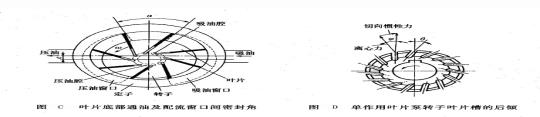
d. In order to prevent the oil suction and pressure chamber from penetrating, the sealing angle p between the oil suction and pressure windows of the valve plate should be slightly larger than the angle between two adjacent blades. However, because the stator of single acting vane pump has no concentric arc section with the rotor, when the closed cavity changes, the oil trapping phenomenon similar to gear pump will occur. However, the oil trapping phenomenon of single acting vane pump is not very serious. The method of opening triangle unloading groove (commonly known as eyebrow groove) on the edge of oil drain window of valve plate can eliminate the harm of oil trapping phenomenon. Sometimes, when the oil in the sealing chamber is compressed to close to the rated working pressure, the sealing chamber is connected to the pressure chamber. Because the pressure difference between the sealing chamber and the pressure chamber is reduced, the hydraulic shock and noise are reduced.